Inspired by Powermonger (Amiga) - Part 3
- educkie
- Oct 19, 2022
- 4 min read

Time to texture the polygons (Area Fill)
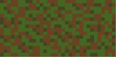
I created the following 8 patterns for various forms of shading. There are 8 separate .iff files. Pattern 1
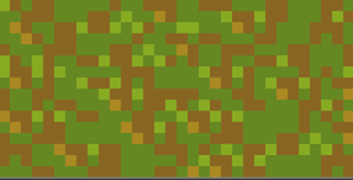
Pattern Shade 1

Pattern Light 1
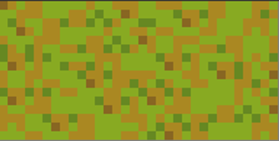
Pattern Dark 1
I’ve gone and created a new class ‘CImage’ from the following intuition struct ‘Image’ It has all the fields I would use to self manage an image. I don't use all of the fields in this demo. But I find this struct handy for other things.
struct Image
{
WORD LeftEdge
WORD TopEdge;
WORD Width
WORD Height;
WORD Depth
UWORD *ImageData
UBYTE PlanePick, PlaneOnOff;
structImage *NextImage;
};
I created a constructor that takes a string (UBYTE*) as a parameter. The string is the file name of the .iff file from where I’m going to extract the image data
//load images
CImage pattern1 = CImage((UBYTE*)"dh0:pattern1.iff");
CImage pattern2 = CImage((UBYTE*)"dh0:pattern2.iff");
CImage pattern_shade1 = CImage((UBYTE*)"dh0:pattern1-Shade.iff");
CImage pattern_shade2 = CImage((UBYTE*)"dh0:pattern2-Shade.iff");
CImage pattern_light1 = CImage((UBYTE*)"dh0:pattern1-Light.iff");
CImage pattern_light2 = CImage((UBYTE*)"dh0:pattern2-Light.iff");
CImage pattern_dark1 = CImage((UBYTE*)"dh0:pattern1-Dark.iff");
CImagepattern_dark2 = CImage((UBYTE*)"dh0:pattern2-Dark.iff");
These files are stored in dh0: The Visual Studio amiga extension provides a folder “dh0” where you can store files. if this was to run from a a floppy disk, then you’d set it to ‘df0:”
This will load (decompress) the .iff image and set the pointer ImageData to the decompressed image data. See the github for this blog to see the decompression in action.
Next I wanted to determine which way the polygons are facing. Ie determine the ‘surface normal’. This is typical for 3d graphics programming. I created a class (Vector3d) to store the supposed 3d coordinates – x, y, z.
//create map as if it 3d
//x horizontal, y height, z depth
//I need this to calculate the normals
for(inty = 0; y < 9; y++)
{
for(intx = 0; x < 18; x++)
{
vertices[y][x].x = x;
vertices[y][x].y = height[y][x/2];
vertices[y][x].z = y;
}
}
The next bit may require some improving…but it gets the job done more or less
I calculate the normal using the typical method. Typically you would get a float/double result. But I’m using whole number. So, either it returns a 0, greater than 0, or less than 0 for any given calculation.
This result helps me identify which direction the polygon is facing and set which texture should be applied for that given coordinate.
I want the light source in the top left corner, so, that means I’ll have shadows falling towards the bottom right corner.
It’s not a perfect system, but creates results.
I’ve set up 2 types. Which just represent whether it’s the first triangle in the square, or the 2nd.
Basic normal calc below.
//type1
//p2-p1
U.x = vertices[y+1][x].x - vertices[y][x].x;
U.y = vertices[y+1][x].y - vertices[y][x].y;
U.z = vertices[y+1][x].z - vertices[y][x].z;
//p3-p1
V.x = vertices[y+1][x+2].x - vertices[y][x].x;
V.y = vertices[y+1][x+2].y - vertices[y][x].y;
V.z = vertices[y+1][x+2].z - vertices[y][x].z;
N.x = U.y*V.z - U.z*V.y;
N.y = U.z*V.x - U.x*V.z;
N.z = U.x*V.y - U.y*V.x;
normals[y][x] = N;
And setting the tile pattern based on the direction of the normal.
if(N.x < 0 && N.z < 0)
TilePattern[y][x] = pattern_light1.ImageData;
else if(N.x > 0 && N.z > 0)
if(N.y > 2)
TilePattern[y][x] = pattern_dark1.ImageData;
else
TilePattern[y][x] = pattern_shade1.ImageData;
else if(N.z > 0)
TilePattern[y][x] = pattern_shade1.ImageData;
else if(N.z < 0)
TilePattern[y][x] = pattern_light1.ImageData;
else
TilePattern[y][x] = pattern1.ImageData;
Ive created a new type of Polygon. TexturedPolygon. It inherits from Polygon
It will store it’s texture and the height of the texture. Now, height is a bit misleading. Height is a power of 2 value that will equal how many words are in the texture.
My textures are 32 x 16. Therefore that’s 32 words. The height is 5 (1 << 5) = 32. (1x2x2x2x2x2)=32.
class TexturedPolygon : public Polygon
{
public:
UWORD *texture;
WORDheight;
TexturedPolygon(){}
TexturedPolygon(Point _p1, Point _p2, Point_p3)
: Polygon(_p1, _p2, _p3)
{
}
TexturedPolygon(Point _p1, Point _p2, Point _p3, UWORD*tex, WORD ht)
: Polygon(_p1, _p2, _p3)
{
texture = tex;
height = ht;
}
};
Here we see the Textured Polygons being set up – using the TilePattern array to set the pattern.
int p = 0;
for(int y = 0; y < 8; y++)
{
for(int x = 0; x < 8; x++)
{
Point p1 = points[y][x]; p1.y -= height[y][x];
Point p2 = points[y + 1][x]; p2.y -= height[y + 1][x];
Point p3 = points[y +1 ][x + 1]; p3.y -= height[y + 1][x + 1];
txPolys[p++] = new TexturedPolygon(p1, p2, p3, TilePattern[y][x*2], 5);
p1= points[y][x]; p1.y -= height[y][x];
p2= points[y][x + 1]; p2.y -= height[y][x + 1];
p3= points[y + 1][x + 1]; p3.y -= height[y + 1][x + 1];
txPolys[p++] = new TexturedPolygon(p1, p2, p3, TilePattern[y][x*2+1], 5);
}
}
Now we are ready to draw.
Still need tell the RastPort we are going to go Textured filling
Set the a (foreground) pen to 255. Set the background pen to 0 and draw mode JAM2
void SetTextureDraw()
{
SetAPen(m_RastPorts[0], 255);
SetBPen(m_RastPorts[0], 0);
SetDrMd(m_RastPorts[0], JAM2);
}
To draw a texture. You need to tell the rastport the pattern being used.
SetAfPt is a macro – I guess it means “Set Area Fill Pen t”?
Parameters are the rastport, the texture and the height (negative for images) Since we are using an image with many bitplanes, we set the height as a negative number.
void DrawTexturedPolygon(TexturedPolygon *tx_poly)
{
SetAfPt(m_RastPorts[0], tx_poly->texture, -tx_poly->height);
DrawFilledPolygon((Polygon*)tx_poly);
}
Iterate over the array of Textured Polygons
for(TexturedPolygon* poly : txPolys)
{
view.ViewPort()->DrawTexturedPolygon(poly);
}
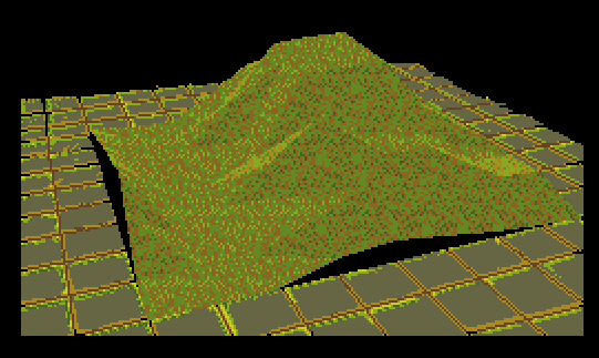
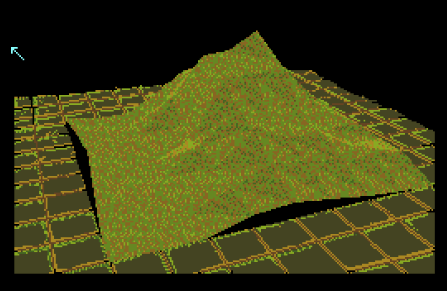
And…

Ok. So, it's really pretty slow.
Obviously, this is not the way it was done. But it proved my theory/idea.
Edit. I forgot about the background image.
I created a new class inheriting from "BitMap" called CBitMap. Like CImiage, the constructor will decompress the file you send to it.
CBitMap background = CBitMap((UBYTE*)"dh0:background.iff");
Now we can send the background to a function that will Blit the bitmap to screen
void BltImg(CBitMap *bm, LONG x, LONG y) { BltBitMap(bm, 0, 0, BitMaps[0], x, y, bm->BytesPerRow<<3, bm->Rows, 0xc0, 0xff, NULL); }
Call this function before drawing the polygons.
yeah, the palette is a bit different.
Now that I've completed this, I can take a look at achieving the same results, but using the hardware directly, instead of the graphics.library
I'll start with c/c++ poking the chips and go from there.
Full code for part 3 here:

Comments